Vibration analyzer (VA-12)

Portable vibration analyzer for Equipment
Diagnosis and On-site Measurements
Vibration Meter VA-12 With FFT analysis function


Vibration Meter Mode

Vibration Meter Mode Applications
Simple Diagnosis
| Vibration magnitude Measuring the magnitude of vibrations is a useful diagnostic technique for ascertaining that machinery is operating normally and checking for signs of possible problems. For example, when vibrations exceeding the reference value in the velocity range (up to 1000 Hz) are detected, the presence of an imbalance, misalignment, or loosening condition can be suspected, whereas vibrations in the acceleration range (1 kHz to about 12 to 15 kHz) point to possible bearing or gear problems.Crest factor The crest factor (C.F.) is an indication of the impact characteristics of a waveform. It is determined by the ratio between the RMS and peak values. Higher crest factor values indicate a stronger impact quality. The crest factor of acceleration measurements is useful for detecting the early stages of bearing damage. Crest factor = Peak value/RMS value The vibration waveform of a bearing with a fault in the initial stage is shown in the example below.
|
 |

Maintenance Management of Machine Equipment
By periodically measuring the vibration magnitude and comparing the results to a reference value, the equipment condition (normal or potential problem) can be diagnosed.
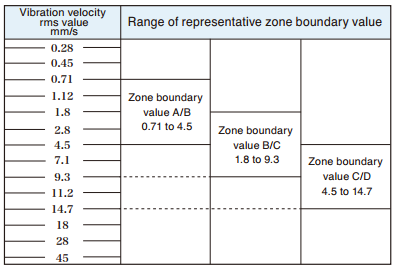
| Using an absolute evaluation standard ISO 10816 series (Evaluation of machine vibration by measurements on non-rotating parts). According to ISO 10816-1:1995 / Amd. 1:2009, evaluation criteria for mechanical vibration over a specified range are to be decided by agreement between the supplier and the user of the machine, and boundary values for evaluation are to be determined in consideration of the measurement position and the support rigidity of the machine etc. Reference value A: Newly installed machinery will normally be within this range. |
Representative zone boundary values
|
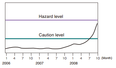
| Using a relative evaluation standard(trend management)
Using the normal condition as a reference, threshold values for caution and hazard conditions are set. |
 Trend management diagram |
FFT Analyzer Mode
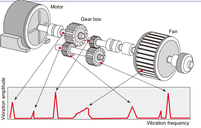
| The Need for Frequency Analysis
Machinery usually comprises a variety of vibration As shown in the illustration, the locations where vibrations occur will affect the vibration frequency. |
 |
 |
 |
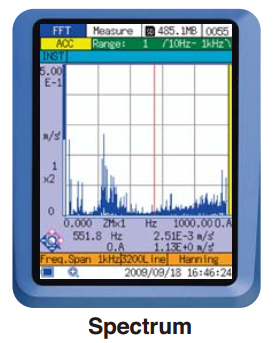
| Vibration amplitudes are shown for each frequency. The time waveform is divided into constant intervals, and FFT analysis* is performed for these intervals.A sine wave will have only one line spectrum, but complex machine vibrations will show peaks at various frequencies.* FFT (Fast Fourier Transform) analysis is a type of frequency analysis that is particularly suited to analyzing machine vibrations. |
This shows the variations over time at the location of the It provides information that is not available from the spectrum display, such as whether the vibration is normal or impact related, whether it has shifted upwards or downwards, etc. |
FFT Analyzer Mode Applications
Product Quality Control
| When testing products on manufacturing lines for unusual vibrations, frequency analysis can be very helpful. For example, when targeting a specific frequency, it can be determined whether there are vibration components in the adjacent frequency range. Using the frequency spectrum with a known good product as reference, comparative analysis can be applied to pass / fail evaluation.
|
 Comparison to reference spectrum(Overlapping of stored data) |
FFT Analyzer Mode Applications
Precision Diagnosis of Rotating Machinery
Precision diagnosis is used to determine the cause of problems as well as the extent, location etc.
| Bearings
Bearing problems will cause a significant increase in acceleration values. |
 |
| Misalignment
When there is a misalignment, large vibration components that are an |
 |
| Imbalance
When there is an imbalance, large vibration components at a frequency equal to the rotation speed will appear in |
 |
Measuring the Resonance Frequency of a Structure
| When an external force at a frequency close to the resonance frequency is applied to a structure, strong vibration will occur. This can lead to breakdown of machinery, product quality degradation, and other problems. In order to guard against such risks, measuring the resonance frequency is very important. In the example shown at right, multiple resonance frequencies at 8 Hz, 98 Hz etc. exist. |
 |
Specifications

|

|
Please contact us if you need assistance.
Thank you


